

Aerospike Engine
Introduction:
It was not long ago when the aerospike nozzle was unknown to all but a handful of rocketry experts. Aside from a spate of research in the early 1970s, the concept of the plug nozzle appeared to be nothing more than a footnote in aersopace history. Though explored by the Germans as early as World War II for use in jet engines, it was not until the unveiling of Lockheed Martin's winning X-33 concept that this type of engine has received widespread attention.
In this site, we will first explore what a rocket nozzle is and compare the three major families of nozzles used to date. Next, the theory underlying the aerospike family of nozzles will be presented. In addition, the advantages and disadvantages of this form of nozzle, in comparison with the traditional converging-diverging nozzle, will be discussed. Finally, we will look at the effort to research, develop, and test aerospike engines, especially those developed for NASA's X-33 launch vehicle.
Rocket Nozzles
Before we can understand what an aerospike nozzle is and how it works, we need to establish some basic terminology and learn about the purpose of a rocket nozzle.
Purpose:
Simply put, the nozzle is the component of a rocket or air-breathing engine that produces thrust. This is accomplished by converting the thermal energy of the hot chamber gases into kinetic energy and directing that energy along the nozzle's axis, as illustrated below.
Simple representation of a rocket nozzle [from Rocketdyne, 1999]
Although simplified, this figure illustrates how a rocket nozzle works. The propellant is composed of a fuel, typically liquid hydrogen (![]() (mdot) where the fuel and oxidizer are mixed and burned. The exhaust gases from this process are pushed into the throat region of the nozzle. Since the throat is of less cross-sectional area than the rest of the engine, the gases are compressed to a high pressure. The nozzle itself gradually increases in cross-sectional area allowing the gases to expand. As the gases do so, they push against the walls of the nozzle creating thrust.
(mdot) where the fuel and oxidizer are mixed and burned. The exhaust gases from this process are pushed into the throat region of the nozzle. Since the throat is of less cross-sectional area than the rest of the engine, the gases are compressed to a high pressure. The nozzle itself gradually increases in cross-sectional area allowing the gases to expand. As the gases do so, they push against the walls of the nozzle creating thrust.
Mathematically, the ultimate purpose of the nozzle is to expand the gases as efficiently as possible so as to maximize the exit velocity (
where
| F | = | thrust force |
| = | mass flow rate | |
| v exit | = | exhaust gas velocity at the nozzle exit |
| p exit | = | pressure of the exhaust gases at the nozzle exit |
| p |
= | ambient pressure of the atmosphere |
| A exit | = | cross-sectional area of the nozzle exit |
Expansion Area Ratio:
In theory, the only important parameter in rocket nozzle design is the expansion area ratio (e), or the ratio of exit area (

Fixing all other variables (primarily the chamber pressure), there exists only one such ratio that optimizes overall system performance for a given altitude (or ambient pressure). However, a rocket typically does not travel at only one altitude. Thus, an engineer must be aware of the trajectory over which a rocket is to travel so that an expansion ratio that maximizes performance over a range of ambient pressures can be selected.
Nevertheless, other factors must also be considered that tend to alter the design from this expansion ratio-based optimum. Some of the issues designers must deal with are nozzle weight, length, manufacturability, cooling (heat transfer), and aerodynamic characteristics.
Rocket Nozzle Shapes
Not all rocket nozzles are alike, and the shape selected usually depends on the application. This section discusses the basic characteristics of the major classes of nozzles used today.
Nozzle Comparisons:
To date three major types of nozzles, the cone, the bell or contoured, and the annular or plug, have been employed. Each class satisfies the previously discussed design criteria to varying degrees. Examples of these nozzle types can be seen below.

Size comparison of optimal cone, bell, and radial nozzles for a given set of conditions [from Huzel and Huang, 1967]
Conical Nozzle:
The conical nozzle was used often in early rocket applications because of its simplicity and ease of construction. The cone gets its name from the fact that the walls diverge at a constant angle. A small angle produces greater thrust, because it maximizes the axial component of exit velocity and produces a high specific impulse (a measure of rocket efficiency). The penalty, however, is a longer and heavier nozzle that is more complex to build. At the other extreme, size and weight are minimized by a large nozzle wall angle. Unfortunately, large angles reduce performance at low altitude because the high ambient pressure causes overexpansion and flow separation.
Bell Nozzle:
The bell, the most commonly used nozzle shape, offers significant advantages over the conical nozzle, both in size and performance. Referring to the above figure, note that the bell consists of two sections. Near the throat, the nozzle diverges at a relatively large angle but the degree of diveregence tapers off further downstream. Near the nozzle exit, the diveregence angle is very small. In this way, the bell is a compromise between the two extremes of the conical nozzle since it minimizes weight while maximizing performance. The most important design issue is to contour the nozzle to avoid oblique shocks and maximize performance. However, we must remember that the final bell shape will only be the optimum at one particular altitude.
Annular Nozzles:
The annular nozzle, also sometimes known as the plug or "altitude-compensating" nozzle, is the least employed of those discussed due to its greater complexity. The term "annular" refers to the fact that combustion occurs along a ring, or annulus, around the base of the nozzle. "Plug" refers to the centerbody that blocks the flow from what would be the center portion of a traditional nozzle. "Altitude-compensating" is sometimes used to describe these nozzles since that is their primary advantage, a quality that will be further explored later.
Before describing the various forms of annular nozzles, it is useful to mention some key differences in design parameters from the conical or bell nozzles. The expansion area ratio for a traditional nozzle has already been discussed. When considering an annular nozzle, the area of the centerbody (

Another parameter particular to this type of nozzle is the annular diameter ratio,
Annular Nozzles I
Having introduced the three principal families of nozzle shapes, we will now look more closely at the two major subclasses of annular, or plug, nozzles.
Radial Out-Flow Nozzles:
Two major types of plug nozzles have been developed to date. They are distinguished by the method in which they expand the exhaust, outward or inward. The radial out-flow nozzle was the subject of much research in the late 1960s and early 1970s. Examples of this type are the expansion-deflection (E-D), reverse-flow (R-F), and horizontal-flow (H-F) nozzles shown in the figure below.
Size comparison of optimal cone, bell, and radial nozzles for a given set of conditions [from Huzel and Huang, 1967]
The name of each of these nozzles indicates how it functions. The expansion-deflection nozzle works much like a bell nozzle since the exhaust gases are forced into a converging throat region of low area before expanding in a bell-shaped nozzle. However, the flow is deflected by a plug, or centerbody, that forces the gases away from the center of the nozzle. Thus, the E-D is a radial out-flow nozzle.
The reverse-flow nozzle gets its name because the fuel is injected from underneath, but the exhaust gases are rotated 180° thereby reversing their direction. Similarly, the fuel in the horizontal-flow nozzle is injected sideways, but the exhaust is rotated 90°.
Judging by the amount of literature obtained on this subject, little work has been done on the R-F and H-F nozzles, and they will not be considered further. The E-D, on the other hand, has been one of the most studied forms of annular nozzles. While similar in nature to the bell nozzle, the most notable difference is the addition of a centerbody. As shown below, this "plug" may be located upstream of, downstream of, or in the throat, with each location resulting in better performance for a given set of operating conditions.
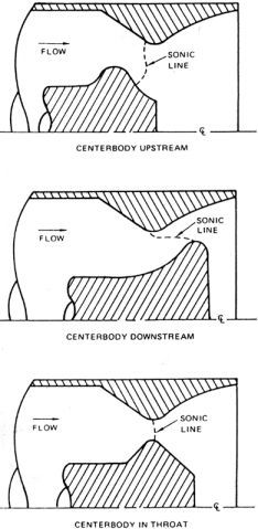
Comparison of centerbody locations in Expansion-Deflection nozzles [from Conley et al, 1984]
The purpose of the centerbody is to force the flow to remain attached to, or to stick to, the nozzle walls, as illustrated in the following figure.
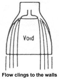
Expansion-deflection nozzle flow behavior at low altitude [from Sutton, 1992]
This behavior is desirable at low altitudes because the atmospheric pressure is high and may be greater than the pressure of the exhaust gases. When this occurs, the exhaust is forced inward and no longer exerts force on the nozzle walls, so thrust is decreased and the rocket becomes less efficient. The centerbody, however, increases the pressure of the exhaust gases by squeezing the gases into a smaller area thereby virtually eliminating any loss in thrust at low altitude.
Annular Nozzles II
Having introduced the three principal families of nozzle shapes and discussed the radial out-flow nozzle, we will now look more closely at the second class of annular nozzles.
Radial In-Flow Nozzles:
The second major variety of annular nozzles is the radial in-flow type, exemplified by the spike shown below.
Size comparison of optimal cone, bell, and radial nozzles for a given set of conditions [from Huzel and Huang, 1967]
This type of nozzle, named for the prominent spike centerbody, is often described as a bell turned inside out. However, the nozzle shown above is only one of many possible spike configurations. Variations of this design, shown below, include
- (a) a traditional curved spike with completely external supersonic expansion
(b) a similar shape in which part of the expansion occurs internally
(c) a design similar to the expansion-deflection nozzle in which all expansion occurs internally.
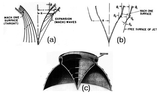
Comparison of spike nozzles with (a) external expansion, (b) internal-external expansion, and (c) internal expansion [from Berman and Crimp, 1961]
Note that each of the above spike nozzles features a curved, pointed spike, the most ideal shape. This spike shape allows the exhaust gases to expand through an isentropic, or constant entropy, process. In so doing, the nozzle efficiency is maximized and no energy is lost because of turbulent mixing in the exhaust flow. While the isentropic spike may be most efficient, it also tends to be prohibitively long and heavy. However, theoretical studies have shown that replacing the curved shape by a much shorter and easier to construct cone results in very little performance loss. The following graph illustrates that the thrust decreases by less than 1% for cone half-angles up to 30°. Furthermore, the graph gives an indication of how much the spike length can be reduced by employing a cone-shaped spike.
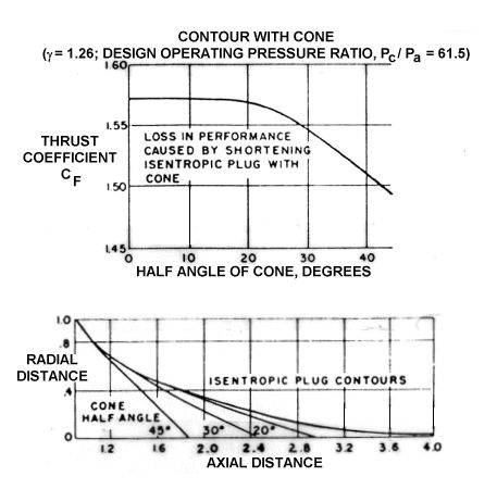
Changes in nozzle performance and length due to replacement of the lower centerbody [from Berman and Crimp, 1961]
Aerospike Nozzles:
Previously, we discussed methods of reducing the length of a spike nozzle centerbody by replacing the ideal spike with a conical spike. While this method does indeed result in a much shorter nozzle length, we can go even further by removing the pointed spike altogether and replacing it with a flat base. This configuration is known as a truncated spike, an example of which is shown below.
Example of a truncated, conical spike [from Berman and Crimp, 1961]
As any fluid dynamicist recognizes, the significant disadvantage of the "flat" plug is that a turbulent wake forms aft of the base at high altitudes resulting in high base drag and reduced efficiency. However, this problem can be greatly alleviated in an improved version of the truncated spike that introduces a "base bleed," or secondary subsonic flow, into the region aft of the base.
Example of an aerospike nozzle with a subsonic, recirculating flow [from Hill and Peterson, 1992]
The circulation of this secondary flow and its interaction with the engine exhaust creates an "aerodynamic spike" that behaves much like the ideal, isentropic spike. In addition, the secondary flow re-circulates upward pushing on the base to produce additional thrust. It is this artificial aerodynamic spike for which the aerospike nozzle is named.
Linear Aerospike:
All of the nozzles we have studied thus far have been annular, or circular when viewed from below. Still another variation of the aerospike nozzle is not an annular nozzle at all. A second approach, pioneered by the Rocketdyne company (now a division of Boeing) in the 1970s, places the combustion chambers in a line along two sides of the nozzle:
Rocketdyne RS-2200 linear aerospike engine [from Flinn, 1996]
This approach results in a more versatile design allowing the use of lower-cost modular combustors. These modules can be combined in varying configurations depending on the application.
Aerospike Aerodynamics
Thrust Characteristics:
The basic thrust characteristics of the aerospike nozzle can be better understood by referring to the following figure.
Example of an aerospike nozzle with a subsonic, recirculating flow [from Hill and Peterson, 1992]
The nozzle generates thrust in three ways. First, the thrusters in the toroidal chamber, located at the base of the nozzle, generate thrust as the fuel is combusted and exhausted. We shall label this thrust component
where
| F thruster | = | thrust force acting on the thruster |
| = | mass flow rate | |
| v exit | = | exhaust gas velocity at the nozzle exit |
| p exit | = | pressure of the exhaust gases at the nozzle exit |
| p |
= | ambient pressure of the atmosphere |
| A exit | = | cross-sectional area of the nozzle exit |
| = | angle between the thrust axis and the vertical |
We previously discussed how nozzles generate thrust when the exhaust gases expand against the nozzle walls. Although we used the bell nozzle to illustrate that discussion, the exhaust gases in a spike nozzle expand against the spike centerbody rather than outer walls. Thus, the expansion of the exhaust gases exerts a thrust force that we will call
where
| F centerbody | = | thrust force acting on the centerbody |
| A centerbody | = | cross-sectional area of the centerbody moving along the nozzle axis |
| p centerbody | = | pressure of the exhaust gases on the centerbody moving along the nozzle axis |
| p |
= | ambient pressure of the atmosphere |
Finally, we mentioned that the aerospike nozzle is so named because an "aerodynamic spike" is created through the addition of a secondary, circulating flow aft of the flat nozzle base. As the supersonic primary flow, consisting of the high-pressure gases exhausted from the thrusters, expands downstream of the base, the primary flow interacts with the subsonic, secondary flow causing it to circulate. This low-pressure flow then re-circulates upward to exert an additional thrust force on the base.
where
| F base | = | thrust force acting on the base |
| p base | = | pressure of the re-circulating flow on the base |
| p |
= | ambient pressure of the atmosphere |
| A base | = | cross-sectional area of the base |
Summing up these three thrust components yields the following relationship for the total thrust force (T) generated by an aerospike nozzle:
Aerospike Flowfield:
The exact nature of the exhaust flowfield behind an aerospike nozzle is currently the subject of much research. The most notable features of a typical aerospike nozzle flowfield are shown in more detail below.
Flowfield characteristics of an aerospike nozzle [from Ruf and McConnaughey, 1997]
The primary exhaust can be seen expanding against the centerbody and then around the corner of the base region. The interaction of this flow with the re-circulating base bleed creates an inner shear layer. The outer boundary of the exhaust plume is free to expand to ambient pressure. Expansion waves can be seen emanating from the thruster exit lip, and these waves reflect from the centerbody contour to the free jet boundary. Compression waves are then reflected back and may merge to form the envelope shock seen in the primary exhaust.
At low altitude (high ambient pressure), the free boundary remains close to the nozzle (see below) causing the compression waves to reflect onto the centerbody and shear layer themselves. The waves impacting the centerbody increase pressure on the surface, thereby increasing the centerbody component of thrust. The waves impacting the shear layer, on the other hand, increase the circulation of the base flow thereby increasing the base component of thrust.
Shadowgraph flow visualization of an ideal isentropic spike at (a) low altitude and (b) high altitude conditions [from Tomita et al, 1998]
As the vehicle ascends, the pressure decreases and the free boundary expands further and further away away from the nozzle contour, as shown above. As it does so, the compression waves also move downstream and eventually cease to impact on the centerbody. The pressure profile on the contour becomes constant and no longer varies with ambient pressure. However, the secondary flow remains under the influence of ambient pressure for a much longer period. Only at very high altitudes do the compression waves impact downstream of the sonic line, at which point the base pressure becomes constant. The primary exhaust is then said to have enclosed the wake.
Altitude Compensation
Altitude Compensation:
To begin our discussion of altitude compensation, we must first understand how a traditional bell nozzle functions as it operates from sea level to high altitude, as illustrated below.
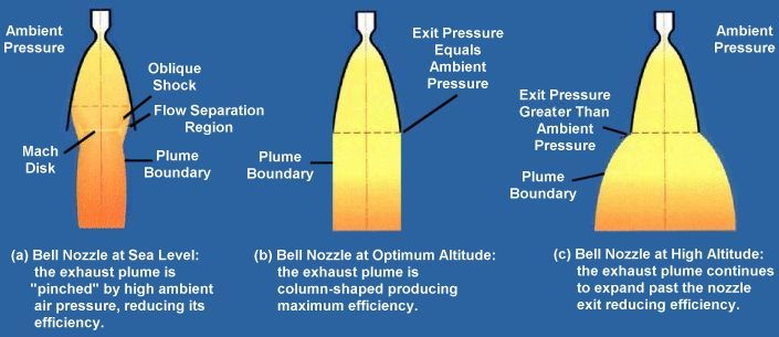
Bell nozzle behavior during flight [from Rocketdyne, 1999]
As discussed in the above figure, bell nozzles suffer from reduced efficiency at low and high altitude because of the difference between the pressure of the exhaust gases and the ambient pressure of the atmosphere. At low altitudes, the exhaust pressure is too low, and the higher atmospheric pressure pushes the exhaust inward. This inequality causes the exhaust to become separated from the nozzle walls reducing the amount of thrust generated. This condition is known as overexpansion. At high altitude, the bell nozzle suffers from the reverse problem. Here, the exhaust pressure is much higher than the ambient pressure causing the exhaust to continue to expand past the nozzle exit. Since the additional expansion occurs outside of the nozzle, that expansion does not exert thrust on the nozzle, so that thrust is lost. This condition is known as underexpansion.
At the optimum altitude, for which the nozzle is tailored during the design process, the exit pressure equals the ambient pressure. Note in the above figure that the exhaust plume becomes column shaped indicating that the exhaust is perfectly expanded thereby maximizing efficiency and thrust. Thus, both overexpansion and underexpansion reduce overall engine efficiency and thrust. If we could somehow minimize the exit area at launch and increase it as the rocket ascends, we could optimize the nozzle for each altitude and maximize the thrust. Such a nozzle, would markedly improve overall performance. An ideal nozzle would be able to continually adjust its contour, area ratio, and length to maximize thrust at each altitude (see the figure below), a concept known as altitude compensation.
Ideal nozzle that continually adjusts its geometry as altitude increases [from Rocketdyne, 1999]
However, a bell nozzle that continually changes its geometry is clearly not practical, and the designer must instead make a series of tradeoffs in selecting the area ratio of a nozzle. The following graph gives some idea of the issues the designer must consider.
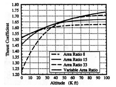
Ideal thrust coefficient for fixed area ratio and continously variable area ratio nozzles [from Ruf and McConnaughey, 1997]
The ideal nozzle, indicated by the thick solid line, represents the maximum performance possible. At low altitudes, we want a small area ratio, meaning the exit area is small, to minimize overexpansion. However, the graph shows that we will pay for this excellent performance at low altitude with underexpansion at high altitude resulting in large thrust losses. The converse is true of a high area ratio--high altitude performance is maximized at the expense of overexpansion and poor efficiency at low altitude.
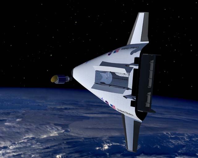
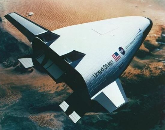
While altitude compensation is certainly desirable in any rocket application, this adaptive quality is a virtual necessity in any Single Stage to Orbit (SSTO) vehicle, like the X-33. Some believe that a reasonably sized payload simply cannot be carried from sea-level to orbit in a one-staged vehicle with current engine technology. Numerous methods of incorporating altitude compensation have been tried. Examples include extendible nozzles that "grow" through flight, "aspirated" nozzles in which ram air is injected into the nozzle to fill the exit and keep flow attached, and a step along the nozzle wall that prevents the flow from overexpanding at low altitude.
However, many claim that the ultimate strength of the aerospike nozzle is its inherent altitude compensation capability, as shown below.
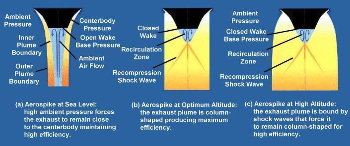
Aerospike nozzle behavior during flight [from Rocketdyne, 1999]
This ideal behavior results from the fact that the outer plume boundary of the primary flow is acted upon only by the ambient pressure of the atmosphere. Recall from our discussion of aerospike thrust characteristics, high ambient pressure at low altitudes forces the exhaust inward increasing the pressure on the "centerbody" and the centerbody component of thrust. In addition, the base region is open to high ambient pressure resulting in a greater "base" thrust component. At design pressure, the flow becomes column shaped, much like a bell nozzle, for maximum efficiency. When operating at low ambient pressure (at high altitude or in a vacuum), the flow is constrained by expansion/compression waves that direct the exhaust axially to maintain the thrust force on the centerbody. At low pressures, however, the nozzle operates in a "closed wake" state. Since the base is not subject to a high ambient pressure, there is no altitude compensation benefit, and the aerospike behaves like a high area ratio bell nozzle. Thus, in theory at least, the aerospike nozzle meets or exceeds the performance of the bell nozzle at all operating pressures.
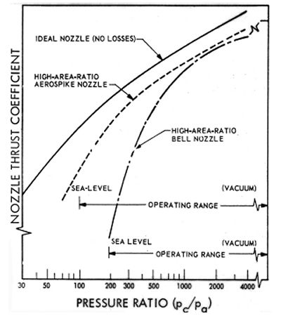
Comparison of theoretical nozzle performance [from Huzel and Huang, 1967]
Performance Losses
Performance Losses:
When we first introduced altitude compensation, we compared a theoretical aerospike nozzle with a bell nozzle and an ideal nozzle. According to theory, the aerospike should meet or exceed the performance of the bell at all altitudes, thanks to its inherent altitude compensation characteristics. However, experimental data shows that these predictions are not necessarily true, for many potential sources of losses exist in the design of a practical engine, as illustrated below.
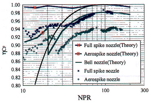
Comparison of nozzle thrust coefficient efficiencies vs. nozzle pressure ratios (NPR) for theoretical and actual spike, aerospike, and bell nozzles [from Tomita et al, 1999]
The most important cause of these losses is the elimination of the full-length isentropic spike previously discussed. The following graph indicates the loss in performance resulting from the replacement of a "full" (80%) spike by a truncated (20%) spike.
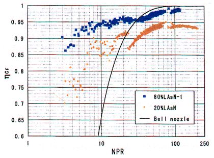
Comparison of nozzle thrust coefficient efficiencies vs. nozzle pressure ratios (NPR) for full (80%) and truncated (20%) spike centerbodies [from Tomita et al, 1998]
Even though the aerodynamic spike does behave similarly to an actual spike, performance will still be lost due to oblique shock formation and the transition from an open to a closed wake. The effect of this transition can be seen in the above figures in the sudden decrease in thrust efficiency at pressure ratios around 20-30. Another important loss results from the replacement of an annular nozzle by a linear one. In a linear engine, exhaust may flow to the side of the engine rather than along its axis, as illustrated in the following figure. Other typical sources of performance loss are usually functions of individual designs, such as the type of thrusters employed and their arrangement, but these are beyond the scope of this discussion.
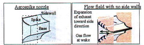
Cross-flow in an aerospike nozzle [from Tomita et al, 1999]
Many researchers working on the X-33 and similar projects in other countries are currently conducting a great deal of research into methods of alleviating these performance losses. The most important of these, already mentioned several times, is the introduction of a secondary flow aft of the nozzle base, or a base bleed. The pivotal question surrounding the secondary flow is how great it should be. Research has shown that too small a bleed has no impact on performance while too large a bleed can have a detrimental effect on overall performance.
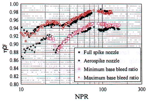
Aerospike nozzle performance with base bleed [from Tomita et al, 1999]
Some experimental results are provided above comparing the full spike, aerospike without base bleed, and aerospike with minimum base bleed (0.3% of the primary flow) and maximum base bleed (2.4%). Beyond a bleed of about 3%, performance begins to suffer because the base flow actually re-circulates too quickly. As indicated in the above figure, the maximum bleed results in far better performance, matching the full spike over a very large range of operating pressures.
The same study also looked at the use of endplates, or sidewalls, along the aerospike, as illustrated below. Two types of sidewalls were evaluated, one extending well into the base flow region and another extending only to the end of the centerbody.
Advantages & Disadvantages
Advantages:
- Smaller nozzle: The truncated spike can be far smaller than a typical bell nozzle for the same performance, as shown below. In addition, a spike can give greater performance for a given length.
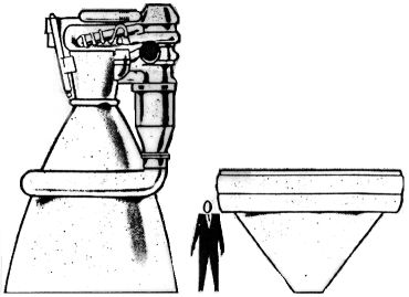
Size comparison of a bell and a plug nozzle [from Berman and Crimp, 1961]
- Superior performance: Altitude compensation may result in greater installed performance.
- Less risk of failure: The aerospike engine uses a simple gas generator cycle with a lower chamber pressure than typical rocket engines reducing the risk of a catastrophic explosion. Although low chamber pressures result in reduced performance, the aerospike's high expansion ratio makes up for this deficiency.
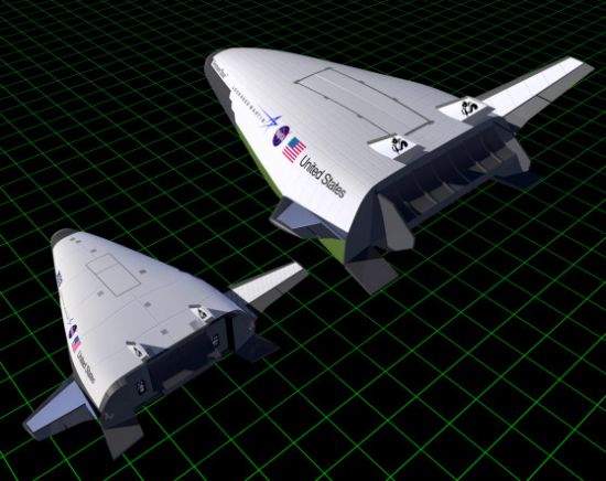
- Lower vehicle drag: The aerospike nozzle fills the base portion of the vehicle thereby reducing a type of drag called base drag.
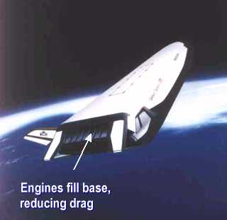
Illustration of aerospike nozzles installed on the X-33 [from Rocketdyne, 1999]
- Modular combustion chambers: The linear aerospike engine is made up of these small, easier to develop, less expensive thrusters that give the engine greater versatility.
- Thrust vectoring: Because the combustion chambers can be controlled individually, the vehicle can be maneuvered using differential thrust vectoring. This eliminates the need for the heavy gimbals and actuators used to vary the direction of traditional nozzles.
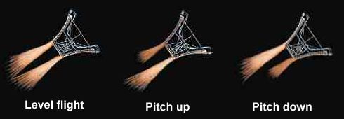
Aerospike thrust vectoring control [from Rocketdyne, 1999]
- Lower vehicle weight: Even though the aerospike tends to be heavier than the bell nozzle, it shares many major structural elements with the vehicle reducing overall weight.
Disadvantages:
- Cooling: The central spike experiences far greater heat fluxes than does a bell nozzle. This problem can be addressed by truncating the spike to reduce the exposed area and by passing cold cryogenically-cooled fuel through the spike. The secondary flow also helps to cool the centerbody.
- Manufacturing: The aerospike is more complex and difficult to manufacture than the bell nozzle. As a result, it is more costly.
- Flight experience: No aerospike engine has ever flown in a rocket application. As a result, little flight design experience has been gained.
Development
Though the concept of the aerospike nozzle has been around for many years, little actual flight or test experience has been available until recently. Nonetheless, we will take a brief look at the effort to develop and test spike nozzles, particularly those used on the X-33.
Early Development:
The first serious studies of spike nozzles were performed in Germany in conjunction with the development of the turbojet engine. Engines, like those used on the Messerschmitt Me 262 shown below, utilized a plug centerbody to vary the throat area for better performance.
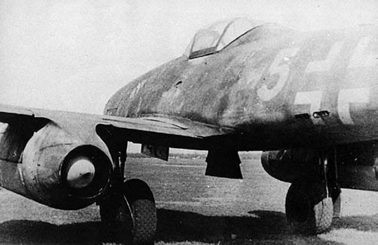
View of the spike centerbody used in the engine nozzle on the Me 262
1950s through 1970s:
NASA, the United States Air Force, and Rocketdyne together spent over $500 million on the development of aerospike engines during the 1950s, 1960s, and 1970s. The development effort, conducted by the NASA Lewis Research Center (now known as NASA Glenn) in Cleveland, OH, and by Rocketdyne's Nevada test facility, tested aerospike engines ranging in size from subscale cold-flow models to a full-scale 250,000 lb thrust engine. These tests included 73 ground tests of full-sized engines totaling over 4000 seconds of operation.
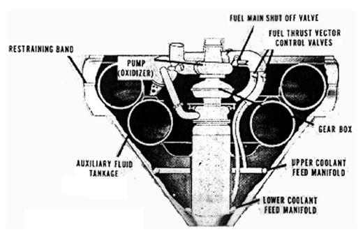
Similar work was underway in West Germany from 1965 to the early 1970s in support of a heavy lift launch vehicle called Neptune. The propulsion arrangement for this concept consisted of a "toroidal plug nozzle" that behaved much like an aerospike with primary and secondary flows.
Current Development:
The early NASA and Rocketdyne research efforts have led to the development of the XRS-2200 linear aerospike engine that was to be used on the X-33 test vehicle. Four of these engines, subscale versions of those planned for the VentureStar vehicle, were built. Two were installed on the X-33 while the other two were being used in ground tests at the NASA Stennis Space Center in Mississippi. Each engine employed 20 combustion chambers, ten aligned on the end of each ramp centerbody, to produce 206,400 lb of thrust at sea level. The full-sized RS-2200 engine intended for the VentureStar was to have 14 combustion chambers (7 per side) to produce 431,000 lb of thrust. The maximum specific impulse of these engines is estimated at 455 seconds. The first two test engines began test-stand testing at NASA Stennis in September 1999. The test program called for 41 firings: 6 initial firings to develop ignition sequencing, 8 to analyze engine performance at different power levels, 11 firings of two separate flight-rated engines, and 16 firings of the two flight-rated engines together.
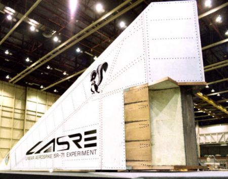
No rocket plug nozzle of any type is believed to have actually flown until the Linear Aerospike SR-71 Experiment (LASRE) began at the NASA Dryden Flight Research Center in 1997.

Flight test of the LASRE aerospike engine mounted on the SR-71
Mounting a 10% scale half-model on the back of an SR-71 Blackbird high-speed research aircraft, NASA engineers used the flights to measure the net thrust, plume expansion, plume aerodynamics, and other parameters of the engine. Tests were to be performed from Mach 0.6 at 15,000 ft to Mach 3.2 at 80,000 feet in an attempt to measure the altitude compensation characteristics of the design.
Closeup view of the LASRE test engine mounted on the SR-71
Although the aerospike engine test program experienced delays, as did the entire X-33 project, the aerospike engine did successfully complete a number of test firings, as illustrated below.
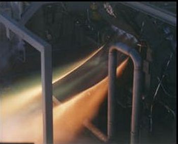
Overhead view of a test firing [from Lockheed, 2001]
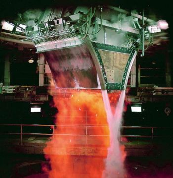
Aerospike engine being test fired [from Lockheed, 2001]
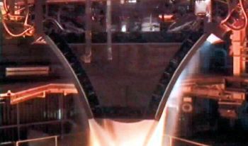
Aerospike engine being test fired [from Lockheed, 2001]
In addition to the US test program, basic research on aerospike engines has also been undertaken in Germany, France, and Japan in recent years. The Japanese research, in particular, is quite interesting as it is intended to support the H-2A rocket and a single-stage-to-orbit (SSTO) vehicle called the HOPE-X. Unfortunately, Japan's sagging economy has caused significant cutbacks in the nation's space program and little more than concept studies and some basic experimental performance results have been generated thus far.
Summary
In 1996, NASA committed itself to the development of a revolutionary new launch vehicle, the X-33. To be successful, this vehicle would require significant advances in rocketry technology, not the least of which are the linear aerospike engines. As we have seen, the strength of this type of engine is its ability to adjust to varying operating conditions resulting in improved off-design performance as compared with traditional converging-diverging nozzles like the bell. While the advantages of this nozzle have been recognized since the 1950s, it has never been utilized in rockets because of the lack of flight-test data and the perceived high risk of using an untried design. Hopefully, this deficiency will soon be rectified allowing the potential of the aerospike engine to be realized.
With NASA's decision to cancel the X-33 after its contract with Lockheed Martin expired in March 2001, the future of not only the aerospike engine, but of the entire single-stage-to-orbit concept remains unclear. However, even if the X-33 never flies, the research conducted by NASA and the Rocketdyne division of Boeing to develop aerospike engines of sufficient performance and reliability to be used on an actual flight vehicle cannot be underestimated.
References
- The Aerospike Engine Frequently Asked Questions List,
https://www.hq.nasa.gov/office/pao/History/x-33/aero_faq.htm - Angelino, Gianfranco. Approximate Method for Plug Nozzle Design, AIAA Journal, vol. 2, no. 10, October 1964, pp. 1834-1835.
- Anselmo, Joseph C. NASA Nears X-33 Pick, Aviation Week & Space Technology, June 17, 1996, pp. 29-30.
- Asker, James R. NASA, Industry Hit Snags on X-33, Aviation Week & Space Technology, June 30, 1997, pp. 27-28.
- Berman, K. and Crimp, F.W., Jr. Performance of Plug-Type Rocket Exhaust Nozzles, ARS Journal, January 1961, pp. 18-23.
- Carroll, B. F. and Dutton, J. C. Transonic Flow in the Throat Region of Radial or Nearly Radial Supersonic Nozzles, AIAA Journal, vol. 23, no. 7, July 1985, pp. 1127-1129.
- Conley, R. R., Hoffman, J. D., and Thompson, H. D. An Analytical and Experimental Investigation of Annular Propulsive Nozzles, AIAA Paper 84-0282, 1984.
- Dornheim. Michael A. SR-71 to Test Aerospike Rocket for X-33 Proposal, Aviation Week & Space Technology, March 11, 1996, pp. 69.
- Dornheim, Michael A. Follow-on Plan Key to X-33 Win, Aviation Week & Space Technology, July 8, 1996, pp. 20-22.
- Dutton, J. C. and Addy, A. L. Transonic Flow in the Throat Region of Annular Supersonic Nozzles, AIAA Journal, vol. 20, no. 9, September 1982, pp. 1236-1243.
- Fick, M and Schmucker, R. H. Linear Aerospike Performance Evaluation, AIAA Paper 97-3305, 1997.
- Flinn, Edward D. Aerospike Engine Powers RLV Savings, Aerospace America, vol. 34, no. 11, November 1996, pp. 18-19.
- Freeman, Delma C. Jr., Talay, Theodore A., and Austin, Robert Eugene Single-Stage-to-Orbit--Meeting the Challenge, Acta Astronautica, vol. 38, no. 4-8, 1996, pp. 323-331.
- Hall, Charles R. and Mueller, Thomas J. Exploratory Analysis of Nonuniform Plug Nozzle Flowfields, Journal of Spacecraft and Rockets, vol. 9, no. 5, May 1972, pp. 337-342.
- Hill, Philip G. and Peterson, Carl R. Mechanics and Thermodynamics of Propulsion. Reading, MA: Addison-Wesley Publishing, 1992, pp. 538-540.
- Hopkins, D. F. and Hill, D. E. Transonic Flow in Unconventional Nozzles, AIAA Journal, vol. 6, no. 5, May 1968, pp. 838-842.
- Humphreys, Robert P., Thompson, H. Doyle, and Hoffmann, Joe D. Design of Maximum Thrust Plug Nozzles for Fixed Inlet Geometry, AIAA Journal, vol. 9, no. 8, August 1971, pp. 1581-1587.
- Huzel, Dieter K. and Huang, David H. Design of Liquid Propellant Rocket Engines. Washington DC: NASA Science and Technical Information Office, 1967, pp. 89-95.
- Korte, J. J., Salas, A. O., Dunn, H. J., Alexandrov, N. M., Follett, W. W., Orient, G. E., and Hadid, A. H. Multidisciplinary Approach to Aerospike Nozzle Design, NASA TM-110326, February 1997.
- Kumakawa, A., Onodera, T., Yoshida, M., Atsumi, M., and Igarashi, I. A Study of Aerospike-Nozzle Engines, AIAA Paper 98-3526, 1998.
- Marshall Space Flight Center Fact Sheets,
https://www1.msfc.nasa.gov/NEWS/background/facts/aerospike.html - Migdal, David. Supersonic Annular Nozzles, Journal of Spacecraft and Rockets, vol. 9, no. 1, January 1972, pp. 3-6.
- Mueller, Thomas J. and Hall, Charles R. Jr. Separated Flow Region within a Planar Expansion-Deflection Nozzle, Journal of Spacecraft and Rockets, vol. 5, no. 6, June 1968, pp. 738-740.
- Mueller, Thomas J. and Sule, Wayne P. Condensation and Probe Interference Effects on Planar Expansion-Deflection Nozzle Experiments, Journal of Spacecraft and Rockets, vol. 6, no. 7, July 1969, pp. 857-859.